Essential for the operation of such a device is the overlap between the electron trajectory and the photon beam. Therefore the undulator modules will be equipped with Beam Position Monitors (BPM) and correctors in order to observe and correct the electron trajectory.
A new microwave concept is considered to design a BPM
capable of detecting beam position with a resolution of a few micrometer.
The monitor system is based on ridged waveguides coupling by small slots
to the magnetic field accompanying the electron beam. The beam position
will be measured in a X-band receiver. A
first prototype of this
monitor was built and tested at the
CLIC
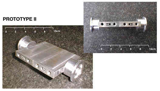
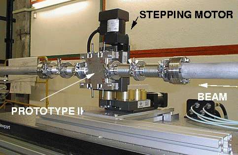
Test Facility at CERN. An improved design
leading to a new prototype was tested at
the S-band Test Facility in Hamburg.
In 1999 one module of the undulator has been equipped with 10 such monitors
including electronics and brought into operation.
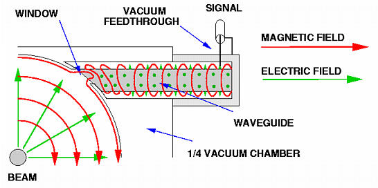
Sketch of the coupling mechanism. The magnetic field accompanying
the electron beam bends through the coupling window into the waveguide
and excites there a mode which travels through the waveguide and will be
linked at the end into a coaxial system. The mode's amplitudes depend on the
position of the beam and are therefore suitable to derive precise beam positions.
The profile shape of the waveguide is one of the key
points in the design. At first it must be designed in a way that a sufficient
amount of the field can couple. Secondly, the cut-off frequency should be below
the beam pipe cut-off to avoid reflecting waves from travelling through
the beamline. 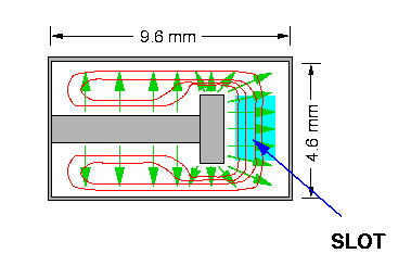 In our design the ridged waveguide serves both constraints.
In addition, the ridge enhances the magnetic field density at the coupling
slot and causes thus an overlap between the magnetic field of the
beam and of the waveguide's fundamental mode. Furthermore, it lowers the
cut-off frequency to the desired value well below the beam tube cut-off
frequency.
In our design the ridged waveguide serves both constraints.
In addition, the ridge enhances the magnetic field density at the coupling
slot and causes thus an overlap between the magnetic field of the
beam and of the waveguide's fundamental mode. Furthermore, it lowers the
cut-off frequency to the desired value well below the beam tube cut-off
frequency.