 |
 |

|

|

|
|
|
|
|
|
|
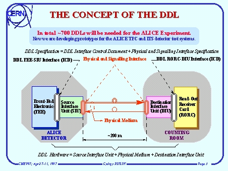
The ALICE DDL will interface the front-end electronics of all the sub-detectors to the read-out receiver cards of the data-acquisition system. The source interface units are connected to the FEEs and placed inside the detector. The destination interface units are connected to the RORCs, located in the counting room about 200 meters from the detector. The two DDL interface units are connected through the physical medium which is a duplex optical fibre. The complete ALICE data-acquisition system will consists of about 700 DDLs.
The DDL interface is defined in the ICD and it will be in fact an ALICE standard. Alternative physical layers can be used for different DDL implementations which are defined in the Physical and Signalling Interface Specification. For the 1st implementation (prototype) of the DDL Fibre Channel physical layer will be used.
Now we developing two different prototypes: one for the ALICE Time Projection Chamber (TPC) and the second for the Inner Tracking System tests.